

Clear electronics/RF guides, videos & downloads by Ian Poole | Resource hub for engineers & hobbyists | Shop: https://xitter.cf/t.co/ClrsfjiAbA
South East, England
Joined November 2016
- Tweets28.5K
- Following269
- Followers17.4K
- Likes2.5K





How to use a Spectrum Analyzer: the key elements.
Spectrum analyzers are probably the most important piece of test equipment for any RF testing, used in design, verification & validation, production test, maintenance and repair and many other RF associated investigations.
Spectrum analyzers can be daunting test instruments when they are first encountered, as their mode of operation may not be quite the ‘norm’ for many people.
But with a little understanding they give a whole new view on RF signals, and hence the RF circuits.
In this video, I detail what a spectrum analyzer is, what the controls are and how to use one.
Check out the video now: youtu.be/WnKK11UEvVE
#spectrumanalyzer #spectrumanalyser #RFtest #RFdesign #electronicsnotes #testmeasurement

Gallium Nitride GaN FETs Explained: do you really know what they are & how they work?
Gallium nitride is a semiconductor material that is being used increasingly to provide improved performance especially in high speed and RF FETs.
The very high electron mobility of gallium nitride, GaN enables the fabrication of semiconductor devices that have a low value of ON resistance combined with a very high switching frequency capability.
These benefits mean that GaN FETs are being used in many new electronic circuit designs for everything from power systems, for electric vehicles and renewable energy applications to RF power amplifiers, other RF design circuits and the like.
GaN FETs use the interface between two semiconductor materials to produce a very thin region known as the 2DEG to provide very high levels of electron mobility that result in GaN HEMTs or high electron mobility transistor being formed. GaN FETs are actually HEMTs although the HEMT term is rarely used.
Often GaN transistor technology is used to fabricate monolithic microwave ICs, MMICs which provide high levels of performance at microwave frequencies.
Check out the link in the comments for a fuller explanation.
#GaN #GaNFET #GanFETs #electroniccomponents

ANENG A3008 Pen Digital Multimeter Review - what is it like.
This DMM boasts a 6000 count solution and quite reasonable accuracy. It also has auto detect for AC and DC voltage and resistance .
It also measures capacitance, continuity (buzzer), temperature and non-contact voltage detection.
It’s basically a great little DmM for not a lot of money.
Watch my video now: youtube.com/shorts/v9xtGZCnW…

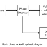
When designing Phase Locked Loops, the filter is probably the most key element in the circuit.
It defines elements like the loop stability, the bandwidth, capture rate, phase noise profile and much more.
Its design is a balance between all these parameters and it is one of the aspects that makes phase locked loop design so interesting.
Check out the full breakdown here: electronics-notes.com/articl…
#phaselockedloop #PLL #RFdesign

Zero-loss X-capacitor discharge technology just got an upgrade.
Reducing no-load standby power without adding design complexity is a constant challenge for power supply designers—especially when meeting strict standards like ErP Lot 6 or aiming for true ultralow standby consumption.
Power Integrations has introduced CAPZero™-4, the 4th generation of their pioneering X-capacitor discharge IC family!
By automatically disengaging the bleed resistors during normal operation and only connecting them when AC power is removed, CAPZero-4 consumes less than 1 mW (under 0.75 mW at 230 VAC). This frees up to 1000 mW of available standby power for the system load.
Key Highlights for Engineers:
🔹 Ultralow Consumption: Enables zero-watt no-load operation for AC-DC converters.
🔹 Drop-in Compatible: Pin-to-pin and package compatible with CAPZero-3 for effortless design migration.
🔹 Extended Thermal Range: Rated from -40 °C to 125 °C for demanding industrial and outdoor applications.
🔹 Global Safety Compliance: Certified to IEC 60335, EN/IEC 62368-1, UL 62368-1, and GB 4943.1.
🔹 Broad Application:Supports X-capacitance from 100 nF up to 6 µF across home appliances, displays, adapters, and industrial power supplies.
With over 1 billion CAPZero ICs shipped since 2010, this generation makes it even easier to meet stringent energy regulations while keeping BOM and layout changes to a minimum.
#PowerElectronics #HardwareDesign #PowerSupply #EnergyEfficiency #Semiconductors #Engineering #ACDC

Multilayer ceramic capacitors, MLCCs are one of the most widely used components these days.
Primarily in they are seen as surface mount components, but there are also leaded varieties.
Find out more in my video: tiktok.com/@electronicsnotes…
@ceramiccapacitors #capacitors #electronicsnotes

Is a Schottky diode the answer to your Power Efficiency & RF Sensitivity Circuit Problems?
A Schottky Diode can be the answer to high-speed switching and many other electronics circuit design performance issues. But it does have some issues.
If you’re designing a power supply or a high-frequency circuit, the "standard" diode might not always be your best option.
Selecting the right electronic component is key. Choosing between a PN Junction and a Schottky Diode can be the difference between it performing well, or not working as you want.
Here is the breakdown of the three "Big Dividers":
1. Forward Voltage (V_f)
* Standard PN: Typically drops about 0.7V. It’s the reliable workhorse, but that voltage drop turns into heat.
* Schottky: Uses a metal-semiconductor junction to achieve a much lower drop, usually 0.15V to 0.45V.
* The Result: Higher efficiency and less wasted power.
2. Switching Speed & Recovery
* Standard PN: These suffer from Reverse Recovery Time. When you switch them off, electrons have to "recombine," causing a brief lag.
* Schottky: They are majority carrier devices. There is virtually no stored charge to dissipate, meaning they switch almost instantaneously.
* The Result: Essential for high-speed switching and RF applications.
3. Reverse Leakage & Voltage
* Standard PN: High "blocking" capability (can handle 1000V+) and very low leakage current.
* Schottky: They are notoriously "leaky" at high temperatures and generally have lower breakdown voltages (usually capped around 100V or a little more for silicon Schottkys).
* The Result: If you need to block high voltage reliably, stick with Silicon or use silicon carbide Schottky diodes.
Where are they used?
* Standard PN Junction: general rectification, high voltage applications, general purpose circuits
Schottky Diode: power supplies, solar panel circuits, RF mixers, RF signal detectors, logic ICs
Pro Tip: Always check your thermal overhead. A Schottky’s low forward voltage is great, but if your environment is already hot, that increased reverse leakage can rocket upwards.
Where have you used either of these diodes?
#diodes #Semiconductors #PowerElectronics #electroniccomponents #TechTips #electronicsnotes

Check out my video explaining more: Schottky Diodes Unpacked: Low Voltage Drop, High Performance -
youtu.be/JBmSv2kitWM
Transistor Common Emitter Amplifier - the most versatile circuit?
The transistor common emitter circuit configuration is used for transistor circuit design. But how useful really is it?
In this video, I explain all about the common emitter amplifier: what it is, its advantages and see some circuit designs.
The transistor common emitter amplifier is probably the most widely used transistor configuration.
First of all, I explain what the Common Emitter Amplifier actually is: it's a circuit that uses a transistor, to amplify an input signal. The "common emitter" part refers to the fact that the emitter terminal is common to both the input and output circuits.
Next I look into how it works: when a small input signal is applied to the base of the transistor, it causes a much larger current to flow through the collector to the emitter. This results in a significant amplification of the input signal.
Here's a list of its chief characteristics:
a) It has a high voltage gain making it ideal for various applications.
b) It offers a moderate input impedance, allowing it to be driven by a variety of signal sources.
c) It has a medium output impedance and this makes it suitable for driving many loads.
Where is it used?
1) As general amplifiers for amplifying everything from audio signals, to almost anything.
2) In RF circuits for amplifying signals in communication systems in both transmitters and receivers
3) They can even be configured as oscillators by providing the right kind of feedback.
The common emitter amplifier is a versatile and fundamental circuit in electronics. Its ability to amplify signals effectively makes it an essential component in numerous electronic devices.
Check out my video now: youtu.be/A0sWlW1o0h0
#transistor #commonemitter #amplifier #circuitdesign #HardwareDesign #HardwareEngineering #electronicsnotes

Reed Relays are a Surprisingly Good Switching Solution.
Ever wonder how electronic circuits achieve fast, reliable, and isolated switching without the bulk of traditional electromechanical relays?
Meet the reed relay - a compact component that bridges the gap between traditional mechanical relays and solid-state alternatives.
What is a Reed Relay?
At its core, a reed relay consists of a reed switch - two overlapping nickel-iron blades hermetically sealed inside a glass envelope filled with inert gas (like nitrogen)—wrapped inside an electromagnetic actuating coil.
When current passes through the coil, it creates a magnetic field that magnetizes the blades. They attract each other, snap shut, and close the circuit. Remove the current, the field drops, and the spring-loaded contacts snap back apart.
Why Engineers Choose Reed Relays:
* Speed: Because the gap between contacts is tiny (0.05 to 1 mm), they boast incredibly fast switching speeds—often between 0.5 to a few milliseconds.
* Reliability & Longevity: Sealed inside glass, the contacts are entirely protected from moisture, oxidation, and contaminants.
* Complete Isolation: They offer absolute physical isolation between the control circuit (coil) and the switched circuit.
* Compact Size: They are small enough to fit into standard SIL or DIL integrated circuit packages, saving precious PCB real estate.
Design precautions:
While they are highly reliable, reed relays aren't always a "set-and-forget" component. When designing them into your circuits, remember:
1. Contact Bounce: The contacts collide with high energy, causing minor "bounces." If switching capacitive or inductive loads, this can cause arcing and reduce contact life.
2. Magnetic Interaction: Unscreened reed relays can experience magnetic coupling. If placed too close together on a PCB, their fields can oppose one another, requiring a higher coil voltage to close.
Pro tip: Always look for reed relays with built-in ferrous metal screens to optimize efficiency and enable tight stacking!
3. Current Constraints: They are typically built for low-to-medium signal switching, not heavy-duty power applications.
From test and measurement matrix switches to automated telecommunication exchanges, the reed relay remains an elegant, trusted solution for modern hardware engineering.
More information- check the link in the comment.
#ElectronicsEngineering #HardwareDesign #CircuitDesign #ElectronicComponents #ElectricalEngineering #electronicsnotes

And also check out my video:
Inside the Reed Switch: How a Tiny Magnet Changes Everything
youtu.be/uCYTTKwsM0g
👉 Want to dive deeper into the history, construction materials (like rhodium and ruthenium coatings), and circuit design considerations? Check out the full guide here: electronics-notes.com/articl…
Why the transformer is still an essential component for modern electronics
While digital technology gets all the headlines, the "analogue" transformer remains a really key electronic component for many circuit designs. But it is probably the least understood of the basic electronics components.
From the power grid to the many domestic devices, transformers are performing key roles behind the scenes.
On my Electronics Notes website, I took a deep dive into how these components function beyond just changing voltage.
Key takeaways include:
🔹 More than Voltage: While we often think of them for step-up/step-down tasks, transformers are vital for galvanic isolation, keeping users safe from high-voltage mains.
🔹 Impedance Matching: In RF and audio design, transformers are essential for maximizing power transfer between different stages of a circuit.
🔹 Diverse Applications: Whether it’s pulse transformers for digital signals or resonant transformers for frequency selectivity, the variety of types (toroidal, ferrite, air-core) is vast.
Even as circuit designs evolve, understanding the magnetic coupling and theory behind these components is a must for any engineer.
Check out the full breakdown in the link in the comments.
#ElectronicsEngineering #ElectricalEngineering #CircuitDesign #TechEducation #electronicsnotes #electroniccomponents

For a deeper look at transformers check out my website: electronics-notes.com/articl…
24 OCTOBER 2026
Fact of the day:
It was on this day in 2003 that the last commercial Concorde flights landed at Heathrow.
Three aircraft landed in sequence having been given special permission to fly low over London before they came in to land at just after 4 pm local time at approximately two minute intervals.
It was sad to see the last flights of this amazing aircraft.
In case you missed my first post - the 2N3055 is an iconic power transistor.
Even though there are more up-to-date devices that can work better, there are still many circuits in which the ‘3055 can be used to great effect.
It’s over 60 years since 2N3055 was first launched, so it has survived well and it’s still being manufactured by many companies.
Find out everything, watch my video now: youtu.be/AlKwDjhUxj8
#2N3055 #transistor #semiconductor #electroniccomponents #electronicsnotes

Understanding Varactor Diodes: what they are; how they work; where they are used
Have you ever wondered how your car radio "tunes" to a station or how your smartphone manages to jump between different frequency bands without a single moving part inside?
The secret lies in a component that combines the worlds of semiconductors and capacitors: The Varactor Diode (also known as the Varicap).
Based on insights from Electronics Notes, here is a look into how this "variable reactor" works and why it’s the key electronic component for modern wireless communication.
What is a Varactor Diode?
At its core, a Varactor is a semiconductor diode designed to take advantage of a phenomenon that most engineers try to minimize: Junction Capacitance.
While a standard diode is meant to conduct or block current, the Varactor is almost always operated in reverse bias. In this state, it doesn't conduct electricity; instead, it acts as a voltage-controlled capacitor.
How It Works:
To understand the Varactor, think of a traditional capacitor (two conductive plates separated by an insulator).
* The Depletion Region: When you reverse-bias a diode, an area empty of charge carriers (the depletion region) forms at the junction. This acts as our insulator.
* The P and N Layers: The conductive semiconductor material on either side acts as the capacitor plates.
* Capacitance Changes: As you increase the reverse voltage, the depletion region widens. In capacitor terms, this is like moving the plates further apart—which decreases the capacitance.
By simply changing the voltage, you change the capacitance. No knobs, no motors, just solid-state physics.
Abrupt vs. Hyperabrupt: The Doping Secret
Not all Varactors are created equal. The way the semiconductor is "doped" during manufacturing changes how it responds to voltage:
* Abrupt Varactors: Have a constant doping level. They offer a linear relationship and a high "Q" (quality factor), making them great for high-frequency precision.
* Hyperabrupt Varactors: Have a non-uniform doping profile that creates a much larger change in capacitance for a small change in voltage. These are the workhorses of wide-band tuning.
Where Do We Use Them?
Without the Varactor, our modern "connected" world would look very different. They are essential for:
✅ Voltage Controlled Oscillators (VCOs): The heart of frequency synthesizers and Phase Locked Loops (PLLs).
✅ RF Filters: Allowing devices to "track" a signal and filter out interference dynamically.
✅ Frequency Modulators: Directly shifting the frequency of a signal to carry information (FM radio).
Pro Tip for Designers
When using a Varactor, the "Capacitance Ratio" is your most important metric. It tells you the range between the minimum and maximum capacitance the diode can achieve. If you need a wide tuning range, go Hyperabrupt; if you need low loss at high frequencies, stick with Abrupt.
Have you ever had to troubleshoot a VCO or a tuning circuit? What’s your go-to Varactor for RF projects?👇
I’ve dropped the link to the full technical guide from Electronics Notes in the comments
#Electronics #RFEngineering #WirelessTechnology #CircuitDesign #RFdesign #HardwareEngineering #Varactor #Semiconductors #electroniccomponents

More information can be found in my website: electronics-notes.com/articl…
ElectronicsNotes by Ian Poole retweeted
The Iconic 2N3055 Power Transistor: the device that changed electronics.
There is a fascinating story behind this iconic power transistor. Not only was it revolutionary when it was introduced, but it has remained a go-to for many applications even to this day - over 60 years after it was launched.
The device is rugged, capable of handling serious power, it is widely available and cheap - what more could you want.
In my video I not only look at its history, but more importantly I look at its performance, its applications, and some points to watch out for as well as a surprising application.
Find out everything, watch my video now: youtu.be/AlKwDjhUxj8
#2N3055 #transistor #semiconductor #electroniccomponents #electronicsnotes
