

We are leading suppliers to #building services contractors, supplying all those diverse products that fix and support #pipework, #electrical systems and #HVAC.
Nottingham, England
Joined August 2016
- Tweets959
- Following797
- Followers930
- Likes81



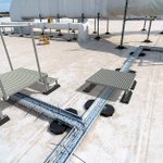

Are your window brackets fitted in pairs on each steel beam?
When connecting M&E channel to steelwork, it’s not uncommon to see just one window bracket used on each beam.
The brackets are designed to work as a pair, with one on each side of the same beam.
Together, they hold the channel perpendicular to the beam flange and help maintain the connection.
There’s another detail that’s easy to overlook: the torque on the cone point screw.
Over-tightening can damage the connection and reduce its clamping strength.
Use a calibrated torque wrench and follow the manufacturer’s specified setting, without exceeding the maximum torque.
Two brackets on each beam and the correct torque on the cone points make a difference to how the channel support is installed.
Watch the video below for a practical demonstration.
6
When should you stop an M&E anchor installation?
Knowing when to pause is just as important as knowing how to install the anchor.
BS 8539 guides the process from anchor selection and specification through to installation, inspection and records.
Installers aren’t responsible for the whole specification process, but they are often the first to spot when something on site doesn’t match it.
So, when should you stop and raise it?
- The anchor isn’t the specified make, type or size.
- The manufacturer’s instructions aren’t available, or the drill diameter, hole depth, embedment or torque setting is unclear.
- The correct drill bit, cleaning equipment, setting tool, torque wrench or socket isn’t available.
- You hit rebar or can’t achieve the required hole depth.
- The substrate differs from what was expected.
- The bracket, fixture, packers, shims, clearance hole or fixing location has changed.
- The hole breaks out, cracks, becomes oversized or behaves unexpectedly.
- The anchor spins, moves, damages the substrate or doesn’t seat correctly.
- You’re asked to use a different anchor or select one without the information needed.
Each of these can affect the conditions the anchor was selected for.
A different fixing location, anchor or embedment may be possible, but the change needs to follow the project’s change-management process before installation continues.
Taking the time to raise the issue helps keep the installation and its supporting evidence connected to the decisions made for the project.

21
Bracket calculations don’t need to be a guessing game.
Whether you’re supporting pipework, cable containment or services across multiple tiers, the bracket design needs to account for the loads and the space available.
That’s where dynaMX® can help.
Enter the bracket dimensions, add the services and their loads, and select whether you’re fixing into concrete or composite decking.
You can then build and review your MX bracket in 3D, rotating the model and refining the configuration before it reaches site.
Once you’re happy with the design, dynaMX® produces a drawing and calculation report based on the details you’ve entered.
That gives your team clear engineering information to support the bracket design, from a straightforward single-tier support to a multi-tier arrangement.
Watch the video to see dynaMX® in action, then explore it using the link in the comments.
What part of bracket design takes the most time on your projects?
19
What makes a tested channel system different from an M&E support assembled using components from different manufacturers?
The answer lies in the evidence available for the finished bracket.
A tested channel system brings specified components and connections together as a defined system.
The components and their common, repeatable connections are independently tested, providing data that can be used to demonstrate the performance of defined bracket configurations.
That doesn’t mean every bracket has been physically tested in its exact final configuration.
It means the system evidence can be applied to the bracket being designed, provided the components, connections and other conditions are within its stated scope.
When components from different manufacturers are combined, the load data for each individual part doesn’t automatically demonstrate how the complete support will perform.
Traceability matters too.
Marked system components can be identified on site, while product information, training records and installation checks can be retained as part of the project record.
So when specifying an M&E support, it’s worth looking beyond whether the components can be assembled.
The important question is whether the available evidence applies to the bracket configuration you intend to install.

4
What does a “fire-rated” M&E support need to demonstrate?
For a multi-service trapeze bracket, the answer starts with the support arrangement and the fire conditions it needs to be assessed against.
The bracket may be carrying pipework, cable tray or other services, each adding to the load it needs to support.
The span, connections, fixings and substrate all form part of the picture, alongside the required fire-resistance period.
With those details defined, the M&E contractor and technical reviewer can consider whether the available evidence applies to the proposed bracket or whether an application-specific assessment is needed.
MIDFIX FRS Design and Evidence helps teams work through the support arrangement, the relevant evidence and any assessment needed for the stated fire condition.
The resulting submission can explain what has been assessed, the assumptions used and the limits of the evidence.
That assessment relates to the support itself, while the performance of the services and the wider fire strategy must also be considered.
Getting the details clear before procurement and installation gives the project team a stronger answer when the fire-performance question is raised.

9
Why does early engagement matter for M&E support design?
Because the decisions made before installation can make a big difference once the project reaches site.
When support details are considered early, the project team has more time to establish the loads, coordinate fixing locations and make sure there’s space to install and maintain the services.
It’s also the time to ask:
- Who is responsible for the support design, calculations and technical submission?
- What product, system and installation evidence will be needed?
- Does the support need to perform under fire conditions, and what evidence will demonstrate that?
- How will changes to the design, products or site conditions be managed?
These questions become harder to resolve once products have been ordered and installation is underway.
A change to the support design may affect procurement, while unclear requirements can leave installers without the information they need.
Early engagement gives designers, contractors and suppliers the opportunity to work through those details together while there is still time to make informed decisions.
It also helps build the Golden Thread from the start, with clear assumptions, responsibilities and records that can be carried through to the completed installation.

5
How do you provide rooftop access over a low-level pipe, cable tray or duct?
The obstruction may be small, but people still need a practical way to cross it when they’re inspecting or maintaining rooftop plant.
A full walkway or larger platform won’t always be needed.
That’s where MX-R Access Low Level comes in.
The modular range includes compact stepover options designed for smaller rooftop obstructions, giving M&E contractors a way to plan access around the services.
Choosing the right arrangement starts with a few details:
- How much clearance is needed over the service?
- Is the access needed for occasional inspection or regular maintenance?
- Where can the feet sit, and how will the roof membrane be protected?
- Is there enough space alongside other rooftop equipment and services?
Considering these points early helps avoid an awkward crossing or a late change when the roof is already busy.
With MX-R Access Low Level, the access arrangement can be sized to suit the obstruction and the people who need to cross it.

7
Can an anchor test confirm a fixing is suitable if the substrate was never properly established?
It depends on what the test was commissioned to do.
An M&E anchor may be specified against a particular concrete or masonry substrate, but what happens if the condition at the fixing location is uncertain?
Before the anchor is finalised, the specifier needs to establish whether the available product data applies to the actual substrate.
Where suitable data isn’t available, testing to determine the allowable resistance may be needed to inform the selection.
That’s a different purpose from proof testing.
Proof testing checks the quality of installed anchors against a defined test load.
A satisfactory proof test does not, on its own, confirm that the anchor was correctly selected for the application.
Getting that distinction clear before the anchor is ordered and installed helps the project team ask for the right test, where testing is needed.
MIDFIX’s Anchor Fixings Strategy brings the selection information, installation guidance, testing and records together, helping the technical submission and site team work from the same anchor specification.
The most useful test report is one that answers the question the project actually needs answered.

7
How does an M&E anchor get from a design specification to a checked installation on site?
Several people are involved, and each decision needs to reach the next person in the process.
BS 8539 provides a practical framework for managing those decisions.
The designer establishes the application requirements, and the specifier selects and specifies the anchor.
The supplier then provides the specified product, manufacturer’s instructions and any product-specific tools needed for installation.
On site, the installer follows the specified method, including the drilling, cleaning, setting, embedment and torque requirements that apply.
The completed installation is then checked and recorded before the anchor is loaded.
But what happens if the specified anchor cannot be supplied, or the site conditions are different from those expected?
The change needs to follow the BS 8539 change-management process, with the specifier or responsible technical party reviewing the proposed alternative.
That review can affect the anchor selection, installation instructions, tools and project records.
For M&E contractors, the value is having a clear process for each stage, with the right information reaching the people who need it.
MIDFIX’s Anchor Fixings Strategy supports that process through anchor selection, technical submissions, fixing boards, training and testing where required.
It also helps teams retain the information needed to explain what was specified, installed and checked.
BS 8539 brings those stages together, helping the project carry the anchor decision through from specification to sign-off.

11
The data behind a tested channel system is only part of the story.
The other part is how the M&E support bracketry is assembled on site.
System data provides evidence for the components and repeatable connections used in a design.
For that evidence to apply to the installed bracket, the specified components and installation methods need to be followed.
Take an M&E support joint, for example.
It may look complete, but if it hasn’t been tightened to the specified torque, its performance may differ from the documented system data.
That’s one reason why installer training matters.
It helps the team understand the components, tools, connection methods and torque settings for the system they are working with.
It also helps installers recognise when a site condition needs to be raised before work continues.
BESA’s TR50 guidance highlights the importance of installation training and supervision for supports and fixings.
A training certificate records that learning has taken place and can contribute towards demonstrating competence.
Skills, experience and behaviours matter too, as do the checks and supervision in place for the actual installation.
For higher-risk building projects in England, Gateway 3 brings the need for reliable project information into focus.
The wider project needs evidence of what was built and how it meets the applicable building requirements.
For an M&E contractor, relevant training records can form part of that picture alongside the specified system, installation checks and supervision records.
Together, they help connect the tested system data to the bracketry that has actually been installed.

1
14
How do your installation teams know which M&E fixings and support components have been specified for each part of a project?
The answer may be in the technical submission, but that information also needs to be easy to find when materials are ordered, issued and installed.
Fixing boards help bring the specification onto site.
They provide a visible reference for the selected products and where each is intended to be used.
That makes it easier for supervisors and installers to identify the correct components, particularly when several similar-looking fixings are being used across a project.
The board also gives the team a starting point for finding the relevant manufacturer’s instructions, setting tools and installation requirements.
If a specified component isn’t available, the board makes the proposed change easier to identify and raise through the project’s change-control process.
Of course, seeing what should be installed is only one part of the picture.
Installation checks and records help show what was fitted, where it was used and whether it was checked against the specification.
That is why MIDFIX includes fixing boards and records within its Anchor Fixings Strategy.
Together with training, supervision and manufacturer guidance, they help carry the original selection through to the finished installation.
The result is clearer information for the team on site and a better record when the project needs to explain what was installed.

10
When a project asks for “fire-rated” M&E supports, what needs to be considered?
The answer starts with the support arrangement and the conditions it needs to perform in.
Before assessing a bracket or support under fire conditions, the project team needs to be clear on the details:
What service is being supported?
What load is the support carrying, and in which direction?
What fire-resistance period is required, and where does that requirement come from?
How is the support fixed, and what is the substrate or supporting structure?
What spans, connections and geometry does the support rely on?
Could deflection affect the services, firestopping or other interfaces?
These details turn a broad request into a question that can be assessed against the project requirements.
MIDFIX Fire Resistant Supports brings the proposed support detail together with the relevant product and system evidence, design approach and technical review.
That helps produce a clearer technical submission, with the arrangement, assumptions and limitations recorded for the project.
For M&E contractors, raising these questions before the support design is fixed or the components are procured gives the team more opportunity to address the requirement.
The question is what the complete support arrangement needs to demonstrate under fire conditions.

6
Above-ground pipework doesn’t always line up exactly as the drawing suggests.
Plinth levels can vary, pipe positions can change and dimensions may need refining once installation begins.
Planning adjustment into the supports gives the site team room to deal with those differences.
Without that flexibility, even a small change can mean cutting, welding or sending a support away for modification.
It can also leave pipework on temporary supports while a revised detail is agreed.
QMEXX Pipe Supports are designed to help with those situations.
The modular system can be assembled and adjusted on site, helping teams accommodate changes within the agreed design without corrective welding or a return to the fabrication workshop.
To get the most from that adjustability, it helps to consider three questions during design:
Where are site dimensions likely to vary?
Which parts of the support can be adjusted, and by how much?
What needs checking before the adjusted support takes the pipe load?
That gives installers a clear understanding of the adjustment available and when a change needs engineering review.
With QMEXX, flexibility can be planned into the installation from the start, helping keep above-ground pipework moving without turning every dimensional change into a fabrication job.

21
Tested channel systems matter beyond the design stage.
A tested system doesn’t transfer design responsibility to the installer.
But once M&E support bracketry is being installed, the contractor may still need to show that the installation matches the specification and follows the system guidance.
That evidence can include:
- The bracket arrangement matches the design information.
- The specified system components have been used together as intended.
- Connections have been installed correctly, including the specified torque.
- Components can be identified and traced through the project records.
A tested channel system gives the project more than data for individual products.
It provides evidence for the system components and their repeatable connections, which can be used to demonstrate the performance of the designed bracket when the stated conditions are followed.
There is another question where fire performance is required.
Ambient load data alone does not demonstrate how an M&E support will perform under fire conditions.
The defined support arrangement needs relevant fire-resistance evidence and, where required, an assessment for the specific application.
For M&E contractors, the aim is to show not only what bracketry was specified, but what was installed and how it is supported by evidence for the conditions it is expected to face.

8
Rooftop space soon gets tight when plant, support frames, pipework, cable tray and maintenance access all need room.
As the design develops, plant positions move, services are added and maintenance requirements become clearer.
The space originally left for a walkway or stepover can quickly disappear.
Plant supports and maintenance access may be designed separately, but they still need to fit together on the same roof.
MIDFIX can review MX-R Roof Supports and MX-R Access together, allowing space for maintenance alongside the plant and its support frame.
That brings walkway positions, stepovers and access requirements into the discussion while the plant layout can still be adjusted.
It gives the project team more opportunity to resolve clashes before the available space is committed.
On a busy roof, considering both together can mean fewer late changes to the walkway, stepover or support layout.
The plant needs room to sit, and the maintenance team needs room to reach it.

20
An M&E support may be secondary steelwork, but its design still needs to work with the rest of the building.
Part 2A of the Building Regulations 2010, as applicable in England, does not restrict design to the main structural frame.
It includes drawings, design details, specifications and calculations prepared for a design.
An M&E support drawing or calculation can therefore be part of the project’s design work, rather than simply a document used to order materials.
That doesn’t make every coordination decision a designer duty, as responsibilities depend on the work being carried out and the requirements that apply.
But when a support is designed for a particular service load, fixing location and configuration, the project information behind it matters.
What will it carry?
What structure will it connect to, and where?
How will the load transfer through the support and fixings into that structure?
Which other services or design details does it affect?
Are there fire-performance or other project requirements to consider?
Answering these questions helps identify what needs confirming with the structural engineer and other designers before the support design is finalised.
Part 2A requires the client to make suitable arrangements, including sufficient time and resources, cooperation between designers and contractors, and provision of relevant building information.
Designers working on one part of the project must also consider directly related design work and report compliance concerns to the principal designer.
For M&E contractors, that means being clear about who is designing the supports, what information they need and how their design connects with other packages.
Calling a support “secondary” doesn’t answer those questions.
Understanding what it carries, what it connects to and who needs to confirm the details gives the support design a clear place in the wider project.

26
Could off-site fabrication take the pressure off your M&E support installation?
Tight programmes, limited working space and restrictions on hot works can make on-site fabrication difficult to coordinate.
Preparing support frames off site moves more of that work into the workshop, leaving the installation team with less to complete on site.
The benefits go beyond installation speed.
Less on-site fabrication
Pre-cut components and pre-assembled frames can reduce cutting, drilling and welding where the supports are being installed.
Earlier quality checks
Dimensions, connections and finishes can be checked before dispatch, helping identify issues before they become site rework.
Better delivery planning
Support packages can be organised around the installation sequence, reducing loose materials and helping manage limited storage space.
More usable working space
Moving fabrication off site reduces the space needed for cutting equipment, materials and assembly, which is particularly useful in congested areas.
Less material waste
Planned cutting and workshop preparation can make better use of materials and reduce offcuts on site.
Coordinated deliveries can also reduce transport movements, although the overall carbon benefit depends on the package and its logistics.
Those gains are strongest when the loads, dimensions, fixing locations and access requirements are confirmed before fabrication begins.
Delivery sizes and handling arrangements need to suit the site too.
MIDFIX Design, Engineering & Fabrication brings those considerations together, from support design and workshop preparation through to delivery planning.
The practical value is straightforward: more work completed and checked before arrival, with less fabrication for the site team to manage.
Where has off-site fabrication made the biggest difference on your M&E projects?

1
20
Substituting an M&E support or fixing can change whether the original supporting evidence still applies.
That doesn’t mean every substitution is wrong.
Availability, programme pressure, cost reviews and unexpected site conditions can all prompt a practical change.
The risk is treating it as a straightforward product substitution without checking what else changes.
A different anchor, channel or fitting can affect the load data, connection performance and installation method being relied on.
It may also require different setting tools, torque values or installation records.
With a tested channel system, substituting a component can mean the published system data no longer covers the assembly.
So “Does it look equivalent?” is only the starting question.
Does the supporting evidence cover the proposed alternative in the actual installation?
That includes the loads, substrate, connections and conditions it needs to work in.
If that is unclear, the proposed substitution needs technical review before it is installed.
Tested support-system data and MIDFIX’s Anchor Fixings Strategy help establish what was specified, which requirements apply and what needs reviewing when a change is proposed.
The aim is to help procurement and site teams solve practical problems while keeping the installation supported by relevant evidence.
That means following the project’s change-control process, obtaining the required acceptance and updating the instructions and records.
A substitute needs more than a matching description on an order.
It needs evidence that it can do the specified job, with the change reviewed, accepted and recorded.

8
Good workmanship on M&E anchors and supports goes beyond what you can see.
An installation can look neat without showing whether the correct method was followed.
Regulation 7 of the Building Regulations requires suitable materials to be properly prepared and fixed for their intended function, with building work carried out in a workmanlike manner.
For M&E contractors, that makes the installation method just as important as the product selected.
The right anchor can still perform poorly if the hole is too shallow, required cleaning is missed, the wrong setting tool is used or the tightening torque is guessed.
A visual inspection of the finished support may not reveal those details.
That is why checks and records need to be part of the installation process, while the work can still be verified.
BS 8539 connects anchor selection, supply, installation, supervision and testing where needed, supported by appropriate records.
Those records help demonstrate that the specified anchor was installed in the intended location, using the required method.
They also give the project team something more useful than reassurance when questions arise later.
So “Does it look right?” is only part of the workmanship check.
What method was required?
Who checked the installation?
What evidence shows that the method was followed?
For safety-critical M&E supports, good workmanship includes both carrying out the installation correctly and being able to demonstrate it.
That still matters when the ceiling is closed and the fixings are no longer visible.

24
Is a calibrated torque wrench really necessary when installing M&E supports?
Where the manufacturer specifies a tightening torque, yes.
“Tight enough” by feel isn’t the same as tightening to the required setting.
For M&E support connections and anchors that rely on torque, correct tightening is part of achieving their stated performance.
Over-tightening can damage fixings or connection components.
Under-tightening can leave insufficient clamping force and reduce connection capacity.
Neither is solved by giving the nut another turn just to be sure.
A calibrated torque wrench helps installers apply the specified setting consistently.
The torque value comes from the manufacturer’s instructions for the particular product or connection, not a universal value in BS 8539.
Getting this right first time helps avoid damaged components, repeat inspections and unnecessary rework.
It also supports the installation evidence requested by the project.
A calibration certificate shows the tool’s accuracy has been checked, while installation records help show where and how the specified torque was applied.
Both matter when the installation needs to be verified.
The practical approach is straightforward: make the required settings available, provide the correct calibrated tools and follow the manufacturer’s tightening method.
Torque control is a small part of the installation process, but it can make a significant difference to connection performance.
How does your team approach torque verification on site?

1
17