

RAYPCB | Since 2005 🌍 🔌 Premium PCB Manufacturing ⚡ Reliable PCB Assembly (PCBA) 💡 Contract EMS Supplier ✨ Fast Turnkey Solutions | Global Shipping
shenzhen
Joined January 2017
- Tweets11.2K
- Following4.2K
- Followers6.9K
- Likes967
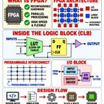





FPGA (Field Programmable Gate Array) is a reconfigurable semiconductor device that allows engineers to create custom digital circuits after manufacturing. Unlike a conventional processor that executes instructions sequentially, an FPGA can perform multiple hardware operations simultaneously.
An FPGA contains thousands of configurable logic blocks (CLBs), programmable interconnections, and input/output blocks.
Each logic block typically contains Look-Up Tables (LUTs) and Flip-Flops (FFs). LUTs implement combinational logic functions, while flip-flops store data and support sequential operations. Programmable routing connects these blocks to form complex digital systems.
The FPGA design process begins with hardware description languages such as Verilog or VHDL. Engineers simulate the design, synthesize the logic, perform placement and routing, generate a configuration bitstream, and program the FPGA.
FPGAs are widely used in wireless communication, radar, aerospace, industrial automation, automotive electronics, image processing, and cybersecurity.
Their major advantages include parallel processing, low latency, hardware flexibility, and high-speed signal processing.

🛡️ Why ESD Protection Doesn’t Stop at the Chip
Many modern ICs include internal ESD protection – but that’s only part of the story.
📄 Datasheet ratings typically show:
▪️ HBM: 2–4 kV
▪️ CDM: 250–500 V
⚠️ System-level requirements (IEC 61000-4-2) can demand:
▪️ 8 kV contact discharge
▪️ 15 kV air discharge
That’s why external ESD protection is still essential – especially for connectors and user-accessible interfaces.
Let’s break down a few common protection circuits 👇
🟡 1. TVS Diodes (still the workhorse)
Normal operation → open circuit
During ESD → avalanche breakdown, surge current diverted to GND
✅ Common applications: USB, HDMI, Ethernet, GPIO lines, power inputs
🔑 For high-speed interfaces: choose low-capacitance TVS (<0.5 pF) to preserve signal integrity.
🟡 2. Rail Clamp Diodes
A simple but effective structure using diodes connected to power rails:
Voltage > VCC → upper diode conducts, clamps
Voltage < GND → lower diode conducts, clamps negative transients
✅ Ideal for MCU GPIO protection and low-speed interfaces.
🟡 3. Unidirectional vs. Bidirectional TVS
Unidirectional → DC power rails (clamps positive transients)
Bidirectional → differential or AC signals (clamps both polarities)
Selection depends on signal type, operating voltage, and interface bandwidth.
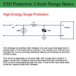
🟡 4. High-Energy Surge Protection (industrial / telecom)
Additional devices come into play:
🔹 GDTs, MOVs, multilayer varistors, polymer suppressors
🔁 Common combo: GDT + TVS
GDT handles large surge energy
TVS provides fast voltage clamping
Layered protection = robust designs in harsh environments.
🎯 The takeaway
Internal ESD structures protect chips during manufacturing & handling.
But system-level ESD protection must be designed at the board level – especially for external interfaces.
👉 In my next post: PCB layout rules for effective ESD protection.
💬 Have you ever faced ESD failures at the system level despite “protected” ICs? Let me know in the comments.
#ESD #CircuitDesign #HardwareEngineering #PCBDesign #EmbeddedSystems


Voltage Regulator Quick Reference: AMS1117 & LM2596S 🔧
Whether you're troubleshooting a repair or selecting a part for your next project, this quick guide breaks down two of the most common voltage regulator families—their output variants and pin configurations.
🔹 AMS1117 Linear Regulators
Common fixed-output variants:
• AMS1117-5.0 → 5.0V
• AMS1117-3.3 → 3.3V
• AMS1117-1.8 → 1.8V
• AMS1117-1.5 → 1.5V
• AMS1117-1.2 → 1.2V
Pinout (1–3): GND · OUT · IN
🔹 LM2596S Switching Regulators
Fixed-output variants:
• LM2596S-3.3 → 3.3V
• LM2596S-5.0 → 5.0V
• LM2596S-12 → 12V
Pin labels:
V-IN
V-OUT
GND
Feedback
ON/OFF
Keep this handy when identifying regulator markings or reviewing pin labels on the bench.
⚠️ Always verify the exact package pinout against the manufacturer's datasheet before making circuit connections.
Created or enhanced with AI tools for creative and educational purposes.
#VoltageRegulator #Electronics #SMD #IC #Tech #Engineering

Deciphering the "Beat": The Physics of IQ Mixing in Doppler Radar 📡⚡
In RF engineering and Electronic Warfare, a target's velocity isn't just a number — it's a frequency shift hidden inside a complex signal.
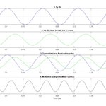
I recently ran a series of simulations at 9.65 GHz to visualize how radar "sees" motion through IQ signal multiplication (mixing). The results (frames Velocity1–Velocity4) offer a clear window into the physics of Doppler processing.
👇 Here's what's happening:
1. The Phase-Coherent Baseline
Every detection starts with the Tx Reference (blue). By comparing it to the Rx Echo (green), we see the time-of-flight delay. As the distance shifts from 2410 m to 5000 m, the phase lag changes — the very foundation of pulse-Doppler processing.
2. Non‑Linear Magic: Signal Multiplication
Multiplying transmitted and received IQ signals isn't just "adding" waves — it's hardware mixing. The result produces a difference frequency: the Doppler shift, or the "beat" frequency we actually care about.
3. Linear Scaling of the Doppler Shift
The simulation perfectly validates the Doppler equation:
fd = 2·v·fc / c
At 10.0 m/s → 0.64 kHz beat
At 20.0 m/s → 1.29 kHz beat (doubles as expected)
At 41.9 m/s → 2.69 kHz beat
Linear, undeniable, and beautifully predictable.
4. Why This Matters for EW & Counter‑Drone Systems
In high‑clutter environments, static objects (buildings, trees) produce a Doppler shift of 0 Hz. By mixing the signals and applying a low‑pass filter (LPF) to the mixer output, we effectively "blind" the radar to anything not moving.
That means we can isolate a fast‑moving drone or vehicle — even when its radar cross‑section (RCS) is tiny compared to the background.
Physics + signal processing + real‑world EW impact. That's the kind of engineering worth diving into.
Have you used IQ mixing for low‑RCS detection or counter‑UAS applications? Let's discuss below. 👇
#RadarEngineering #SignalProcessing #MATLAB #ElectronicWarfare #RFDesign #DopplerEffect #DeepTech #ElectricalEngineering #DigitalSignalProcessing #DSP #RF #RFEngineering #CommunicationEngineering #WirelessCommunications #EngineeringLife #FrequencyDomain #TimeDomain #ActiveRadar #Radar


🚀 Bootloader in Embedded Systems – The First Code That Runs
When an embedded device powers on, your application isn't the first to run.
A Bootloader takes control first.
It initializes the system and decides what happens next.
Let’s break it down 👇
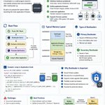
🧠 What is a Bootloader?
A small program stored in non-volatile memory that runs immediately after reset or power‑up.
Its job → prepare the hardware, then launch the main firmware.
⚙️ What a Bootloader Does
✅ Initializes hardware peripherals
• Clock & memory setup
• GPIO / UART configuration
✅ Verifies firmware integrity
• Checksum / CRC validation
✅ Loads the main application
• Jumps to application code
✅ Supports firmware updates
• UART, USB, CAN, OTA
🔄 Typical Boot Flow
Power ON → Bootloader starts → Hardware init → Firmware verification → Jump to application
💡 Types of Bootloaders
🔹 Primary – Stored in ROM/internal flash, runs immediately after reset
🔹 Secondary – Handles advanced tasks like firmware updates
📌 Why Bootloaders Matter
• Secure firmware updates
• Recovery from corrupted firmware
• Remote upgrade capability
• Essential for production devices
💻 Code Example (Jump to Application)
c
#define APP_START_ADDRESS 0x08004000
typedef void (*AppFunction)(void);
void jump_to_application() {
AppFunction app_entry;
app_entry = (AppFunction)(*((volatile uint32_t*)(APP_START_ADDRESS + 4)));
__set_MSP(*(volatile uint32_t*)APP_START_ADDRESS);
app_entry();
}
⚠️ Common Challenges
• Secure boot implementation
• Handling flash corruption
• Memory partitioning
• Update failure recovery
🎯 Key Insight
A bootloader is the foundation of embedded startup – enabling secure boot, reliable updates, and robust system initialization.
💬 What’s your experience with bootloaders? Ever faced a tricky update failure? Let’s discuss below.
#EmbeddedSystems #Bootloader #FirmwareDevelopment #EmbeddedEngineering #IoT

🚀 The Evolution of Radar Arrays: From Passive to Digital Dominance
Radar technology has come a long way—from rigid analog architectures to agile, software-defined systems that are redefining sensing and surveillance.
Let’s break down the journey:
🔹 Passive Array
Centralized high-power amplifier + analog beamforming.
✅ Robust
❌ Limited flexibility and scalability
🔹 Active Array (AESA)
Distributed T/R modules enable electronic beam steering, improved reliability, and multi-target tracking.
✅ Major leap in performance and resilience
🔹 Digital Array
Full digital beamforming with per-element A/D conversion + DDS.
✅ Simultaneous multi-beam operation
✅ Adaptive waveform control
✅ Enhanced ECCM
✅ Superior target discrimination
💡 Key takeaway:
This isn’t just an upgrade—it’s a paradigm shift. Digital arrays bring software-defined flexibility, making radar systems smarter, faster, and mission-ready for complex operational environments.
📡 From legacy systems to cutting-edge architectures, radar continues to drive innovation across defense, aerospace, and beyond.
What stage of this evolution are you most excited about? Let’s discuss below 👇
#Radar #AESA #DigitalBeamforming #DefenseTechnology #Aerospace #SystemsEngineering #Innovation #SignalProcessing

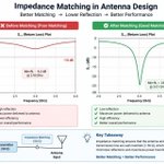
Understanding Impedance Matching in Antenna Design 📡
Impedance matching is a fundamental concept in RF and antenna engineering. It ensures maximum power transfer from the transmission line to the antenna—without it, even the best antenna structure can underperform.
🔹 Why 50Ω?
For optimal performance, an antenna’s input impedance should be as close as possible to the standard reference impedance of 50Ω.
🔹 Matching at a glance:
Z ≈ 50Ω → Ideal matching
Small mismatch → Acceptable performance
Large mismatch → Poor performance
In practice, perfect matching is rarely achieved. Mismatches cause signal reflections, which are measured using parameters like return loss and VSWR. When reflection occurs, part of the signal never gets transmitted, leading to:
❌ Power loss
❌ Lower efficiency
❌ Reduced overall system performance
That’s why engineers focus heavily on matching antenna impedance to the transmission line.
🔧 In my work with CST Studio Suite, I optimize matching by tuning parameters such as feed position, dimensions, and material properties. Getting the antenna impedance and transmission line to work in harmony is always a top priority.
#AntennaDesign #RFEngineering #MicrowaveEngineering #WirelessCommunication #EEE #Research #CSTStudio #Engineering

RO4350B: Built for RF Design
Explore Rogers RO4350B high-frequency PCB material: a glass-reinforced hydrocarbon/ceramic laminate for RF and microwave circuits. Start with the frequency range, loss budget and fabrication requirements before selecting your stackup. #RO4350B #RogersPCB #RFDesign #PCBDesign #RAYPCB
🤖 Made with AI

How to Properly Measure Capacitance on a Circuit Board #Multimeter Usage #How to Measure Capacitance
From simple current-to-voltage conversion to the heart of high-speed optical links – the evolution of the Transimpedance Amplifier (TIA) 📡⚡
TIAs are the unsung front-end heroes of optical receivers, converting tiny photocurrent from a photodiode into usable voltage. What started as a basic interface has become a critical enabler of performance and efficiency in modern optical systems.
🔹 1970s – The beginning
Early TIAs used op-amp based conversion, sufficient for low data rates. But as speeds increased, the RC time constant at the input (dominated by photodiode capacitance) became a bottleneck.
🔹 2000s – Entering the RF domain
Low-input-impedance topologies (common gate, regulated cascode) emerged. Inductive peaking, multi-stage amps, and impedance matching balanced gain, bandwidth, and noise. The feedback resistor became a key tradeoff node.
🔹 2010s – PAM4 and linearity
Multi-level signaling made distortion a major concern. TIAs began integrating equalization, programmable gain, and adaptive biasing to maintain linearity.
🔹 Device & packaging realities
Higher photodiode responsivity = higher capacitance = lower bandwidth. CMOS offers integration; SiGe and InP deliver speed. Packaging parasitics now dictate high-frequency performance.
🔹 Today – 800G / 1.6T era
Photonic integration and co-packaged optics reduce parasitics. With AI data centers pushing to offload DSP, more functionality is moving into the analog front end – TIAs are absorbing equalization, gain control, and calibration.
🔜 Looking ahead
Optical I/O will move closer to ASICs. Expect ultra-low-power designs, adaptive analog front ends, and heterogeneous integration to define next-gen systems.
From a simple converter to a core system component – the TIA continues to evolve, shaping the future of high-speed, energy-efficient communication.
What trends do you see shaping analog front-end design in the next 5 years? Let me know below 👇
#TransimpedanceAmplifier #OpticalCommunications #HighSpeedDesign #Semiconductors #PAM4 #CoPackagedOptics #AnalogDesign

7 Tips for Routing Controlled Impedance Traces 🧵⚡
Controlled impedance routing is one of the most critical aspects of high-speed PCB design.
Small layout mistakes can cause signal integrity problems, reflections, EMI, and unstable communication.
Here are 7 practical tips I always follow when routing controlled impedance traces:
✅ Keep differential pairs symmetrical and parallel
✅ Use uniform via placement to avoid plane discontinuities
✅ Apply proper length matching techniques
✅ Avoid routing over split planes
✅ Keep differential pairs on the same layer whenever possible
✅ Maintain symmetry around coupling capacitors
✅ Add stitching vias close to signal transitions
Good PCB design isn’t just about making connections — it’s about ensuring signal quality and reliability across the entire system.
Which of these rules do you consider the most important in your PCB layouts? 👇
#PCBDesign #HardwareDesign #ElectronicsEngineering #AltiumDesigner #SignalIntegrity #HighSpeedDesign #EmbeddedSystems #Electronics #PCBlayout #Engineering

Analog Circuit Design Interview Question
Consider a 5-transistor OTA. The DC voltage at the gate terminals of M1 and M2 is the same. M1 has 4 times the W/L ratio of M2.
Derive the single-ended differential gain Ad = vout / vid = vout / (Vin1 - Vin2) in terms of transistor parameters and the biasing current.
Will the biasing current be equally divided between M1 and M2 regardless of their W/L ratio, or will it depend on W/L?
Share your answers and reasoning below.
#AnalogCircuits #OTA #InterviewPrep #Engineering

IR Drop in Physical Design – The Silent Performance Killer ⚡
Your timing report looks clean. But if IR Drop isn’t managed, the chip can still fail in silicon.
In VLSI Physical Design, power integrity is just as critical as timing closure.
Let’s break it down 👇
What is IR Drop?
A voltage drop caused by current flowing through the resistance of the power delivery network (PDN).
📐 Based on Ohm’s Law: V = I × R
I = Current drawn by the circuit
R = Resistance of metals / vias
Types of IR Drop
🔹 Static IR Drop
Due to average current flow. Depends on cell density and power grid strength. Seen during steady‑state operation.
🔹 Dynamic IR Drop
Caused by switching activity. Sudden current spikes → voltage droop. Critical near clock edges and high‑switching blocks.
Why IR Drop is Dangerous
❌ Slows down cells → timing violations
❌ Setup / hold failures
❌ Functional errors
❌ Increased leakage variability
❌ Chip failure in worst cases
Root Causes
Weak power grid (thin metals)
High current density regions
Poor via connectivity
Long power routes
Uneven cell placement
How to Fix IR Drop 🛠️
✅ Use wider metal layers for VDD/VSS
✅ Add more power stripes / straps
✅ Strengthen power rings
✅ Improve via stacking
✅ Optimize cell placement (reduce hotspots)
✅ Use decap cells for voltage stability
Analysis Techniques
📊 Static IR Analysis → Average voltage drop
📈 Dynamic IR Analysis → Peak voltage droop
Tools: RedHawk, Voltus, PrimeTime PX
Key Insight
Even a small voltage drop can:
Increase delay
Break timing
Impact reliability
Final Thought
In Physical Design: Power Integrity = Timing Integrity
Ignoring IR Drop is like building a highway without checking the fuel supply — eventually, everything stops.
#VLSI #PhysicalDesign #IRDrop #PowerIntegrity #ASIC #Semiconductor #ChipDesign #VLSIDesign

Recently, during a BGA via‑in‑pad discussion, I received a few recurring questions:
◼ Can a non‑conductive epoxy‑filled via‑in‑pad eliminate a via stub?
◼ How do vias affect thermal performance in high‑current nets?
◼ Are copper‑filled vias the same as conductive‑epoxy‑filled vias?
These often get grouped together, but only the first is truly specific to via‑in‑pad. The other two are general via design considerations that frequently come up in BGA routing.
So let’s clarify what via‑in‑pad actually means — and what it doesn’t.
⚪ What Via‑in‑Pad Really Means
In fine‑pitch BGA routing, vias are sometimes placed directly inside pads because there’s no space between pads.
But via‑in‑pad is not simply “a via drawn on a pad.”
If a standard via is placed in a BGA pad, solder can wick into the hole during reflow, causing unreliable joints.
That’s why a true via‑in‑pad requires filling and capping (IPC‑4761 Type VII) to create a flat, solderable surface.
⚪ Real‑World Layout Options
Centered microvias
Offset (dogbone‑style) via‑in‑pad
Blind via‑in‑pad (to control stub length)
Each choice trades off routing density, cost, and manufacturing complexity.
⚪ Signal Integrity – The Via‑in‑Pad‑Specific Question
When a via‑in‑pad is properly filled and capped, it no longer behaves like an open via stub from a signal integrity perspective.
That’s why filled via‑in‑pad structures are widely used in high‑speed and RF BGA designs.
⚪ Thermal & Fill Material – Broader Via Considerations
Beyond via‑in‑pad, vias also affect thermal and current performance. Multiple vias, larger drills, and connections to inner planes help spread heat and reduce current density.
Fill material matters:
Copper‑filled vias → excellent current & thermal conduction
Conductive‑epoxy‑filled vias → far less conductive; chosen for planarity or process reasons, not performance
These considerations apply to any via, not just via‑in‑pad.
📌 A DFM Note
Via‑in‑pad is a defined manufacturing process — not a layout shortcut.
Many questions raised in via‑in‑pad discussions are actually about general via behavior. Separating the two avoids confusion and leads to better design and DFM decisions.
“Good design is buildable design.”
What’s your biggest challenge with BGA via‑in‑pad? Let’s discuss below. ⬇️


Common PCB defects do not announce themselves until the damage is done. By then, the cost is measured not just in rework hours but in warranty claims, customer trust, and production downtime.
The challenge? Some defects are difficult to identify through visual inspection alone.
A reliable inspection strategy includes:
🔹 Visual Inspection – Identify visible signs of poor wetting or irregular solder joints.
🔹 AOI – Detect visible soldering defects and component placement issues.
🔹 X-Ray Inspection – Evaluate hidden solder joints, particularly those under BGA components.
🔹 Electrical Testing – Verify circuit connectivity and identify functional failures.
👉 Welcome to the discussion. Feel free to share your experience.

ESD Protection in PCB Layout: 6 Practical Guidelines
ESD can quietly ruin a robust design. Here are several proven layout practices to keep your electronics safe.
🟡 Optimize impedance around the TVS
Every trace has parasitic inductance. In a typical protection path, you’ll find inductance between:
ESD source → TVS
TVS → GND
TVS → protected IC
🔑 Key principle:
Make the impedance between TVS and IC higher than the path from the ESD source to the TVS. This forces the surge current into the protection device — not your IC.
🟡 Limit EMI from ESD pulses
Fast voltage transitions from ESD can radiate strong EMI. Nearby traces act like antennas or capacitive couplers, spreading energy into other circuits.
✅ How to reduce coupling:
Isolate protection areas from sensitive signals
Don’t route unprotected signals near ESD paths
Use short, direct traces
Avoid sharp routing angles
🟡 Use vias carefully
Vias add inductance. If your signal path from the ESD source to the IC includes vias before the TVS, some ESD energy may bypass protection.
👉 Best practice:
Keep the ESD source and TVS on the same layer. Avoid vias between them — ensure the ESD current hits the TVS first.
🟡 Place the ESD suppressor properly
Position the TVS as close as possible to the ESD entry point (USB, HDMI, Ethernet, external cables). The goal: intercept the surge immediately.
📌 Golden rule:
Connector → TVS → protected IC
Order is everything.
🟡 Avoid vias between ESD source and suppressor (even when unavoidable)
If vias can’t be avoided, be extra careful. Wrong routing can steer ESD current toward the IC before reaching the TVS.
A better compromise:
Keep the TVS directly in the signal path
Place the protected circuit downstream of the suppressor
🟡 Provide proper grounding
A TVS is only as good as its ground connection. High-impedance ground kills clamping performance.
✅ Recommended:
Connect TVS directly to the ground plane
Use multiple ground vias
Keep the ground path short and wide
This creates a low-impedance path for safe ESD dissipation.


Top 5 SMT Defects That Cost You $10,000+ (And How to Avoid Them)
Most people assume SMT is fully automated.
❌ It’s not.
In fact, that misconception costs the electronics industry $10 billion every year.
Even with million-dollar high-speed pick-and-place machines and advanced reflow ovens, defects still happen daily.
The worst part? 80% are completely preventable.
And they almost always trace back to one of these 5 common defects:
🔹 Solder bridges → Direct short circuit = entire board scrapped
🔹 Tombstoning → One side of component lifts = open circuit
🔹 Cold joints → Unreliable contact = field failures
🔹 Insufficient solder → Weak connection = breaks during shipping
🔹 Misalignment → Placement errors = costly rework
I’ve seen each of these cost a company $50,000+ in a single batch.
⚠️ The real insight?
None of these were random accidents.
They all came down to the same 3 tiny process variations — ones that 90% of EMS factories ignore to save 10 minutes a day.
And those 10 minutes often lead to $10,000+ in rework:
• Bad stencil design
• Uncalibrated reflow temperature profiles
• Outdated placement machine calibration
In EMS, a 0.01mm mistake in stencil design can become a $100,000 loss in production.
✅ How we eliminate these defects before they happen
This isn't rocket science. It's just doing the basics right — the basics that 90% of factories skip to save 10 minutes.
❌ Typical factory✅ What we do
One-size-fits-all stencilsCustom stencils for every component
Calibrate rarelyCalibrate weekly + verify per batch
Occasional placement checksDaily placement accuracy checks
No FAI100% First Article Inspection (FAI)
AOI onlyAOI + X-ray for all hidden joints
Manufacturing isn't just about machines. It's about control, precision, and refusing to cut corners.
If you're an engineer, mastering these basics will save you more time, money, and headaches than any new machine ever will.
👇 Which of these defects has given you the worst headache? Drop a comment below.
#SMT #PCBA #ElectronicsManufacturing #QualityControl #LeanManufacturing
